How to Choose Solder for Electronics

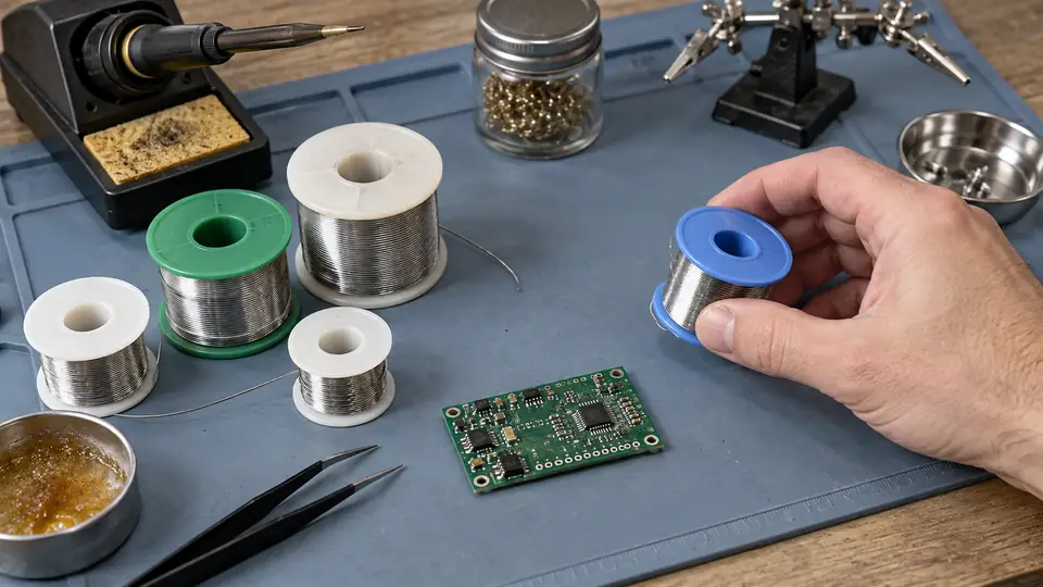
Choose solder by matching four characteristics to the work: alloy, flux chemistry, wire diameter or paste form, and process requirements. For general hand-soldered electronics, flux-cored wire made for electronic assembly is the usual choice. Plumbing solder and acid-core products should be excluded because their aggressive flux residues can corrode electronic connections.
A practical default for unrestricted hobby work is a small-diameter rosin or no-clean flux-cored wire in either Sn63/Pb37 leaded alloy or a recognized lead-free electronics alloy. The better choice depends on regulatory requirements, the existing assembly, available temperature control, cleaning plans, and personal handling preferences.
Start With the Application Requirements
Before comparing alloy labels, identify the constraints of the project. A repair to vintage equipment has different needs from assembling a new lead-free PCB, and hand soldering calls for a different product form than stencil printing and reflow.
Check these points first:
- Compliance: Determine whether the assembly must meet RoHS, workplace, customer, or industry-specific material requirements.
- Existing solder: For repairs, consult service documentation or manufacturer information when available. Matching the established alloy and process reduces uncertainty.
- Assembly method: Hand soldering commonly uses wire. Reflow work generally uses solder paste formulated for the intended process.
- Joint size: Fine-pitch pads need precise solder delivery, while connectors, terminals, and heavier wires consume more material.
- Cleaning: Flux residue requirements affect which flux chemistry is suitable.
- Operating conditions: High-temperature, high-reliability, high-vibration, or regulated applications may require a specified alloy and qualified process.
If a drawing, bill of materials, repair manual, or process specification names an alloy or flux, follow that requirement rather than substituting a convenient spool.
Choose Between Leaded and Lead-Free Solder
The most visible alloy decision is whether to use leaded or lead-free solder. Both can produce reliable electronic joints under a suitable process, but they differ in melting behavior, handling, compliance, and safety practices.
| Alloy family | Relevant characteristics | Typical selection reasons |
|---|---|---|
| Sn63/Pb37 | Eutectic tin-lead alloy. Melts and solidifies at approximately 183°C without a pasty range. | Hand assembly, prototyping, and repair where lead is permitted and compatible with the existing equipment. |
| Sn60/Pb40 | Common tin-lead alloy with a narrow melting range rather than a single melting point. | General hand soldering where lead use is permitted. Care is needed to avoid movement as the joint solidifies. |
| SAC305 | Nominally 96.5% tin, 3% silver, and 0.5% copper. Melts at a higher temperature than tin-lead solder. | Lead-free PCB assembly and repair where this alloy matches the required process. |
| Tin-copper lead-free alloys | Typically less expensive than silver-containing alloys. Their wetting and working behavior differ from tin-lead and SAC formulations. | Lead-free work where the specific alloy is approved for the assembly and process. |
| Specialized alloys | May be formulated for low-temperature processing, high-temperature service, or other controlled applications. | Assemblies that explicitly specify the alloy. These products should not be treated as universal substitutes. |
When Leaded Solder Makes Sense
Sn63/Pb37 is popular for manual work because its eutectic behavior provides a clear transition between liquid and solid states. It generally wets readily under appropriate conditions and can be easier for a beginner to control than many lead-free formulations.
Lead-containing solder is unsuitable where regulations, customer requirements, workplace policy, or product specifications prohibit it. Use dedicated labeling and sensible contamination controls if leaded and lead-free work share a bench.
When Lead-Free Solder Is the Better Choice
Lead-free solder is appropriate for compliant new assemblies, products already manufactured with a specified lead-free process, and users who prefer to keep lead out of their work area. It usually requires a higher working temperature than traditional tin-lead solder, but the iron setting must still reflect the joint, tip, station behavior, flux, and component limitations.
Do not compensate for poor wetting by continually raising the temperature. Check surface cleanliness, flux activity, tip condition, contact area, and the thermal demand of the joint. A tip with useful contact area may transfer heat more effectively than a needle-like tip at a hotter setting.
Do Not Assume “Silver Solder” Identifies One Product
The term silver solder is ambiguous. Some electronic solders contain a small percentage of silver and are soft solders used at normal electronic assembly temperatures. The same term is also applied to hard silver-brazing alloys that require much higher temperatures and are inappropriate for ordinary PCB work. Read the full alloy designation and intended application rather than relying on the front-label description.
Select the Right Flux
Flux removes light surface oxides and helps molten solder wet the metals being joined. For hand soldering, flux is commonly contained in one or more cores inside the solder wire. Extra compatible flux can help during rework, drag soldering, or work on oxidized surfaces, but more flux is not a substitute for clean, solderable materials.
| Flux category | Practical characteristics | Suitable uses and cautions |
|---|---|---|
| Rosin and mildly activated rosin | Common choices for electronic hand soldering. Residue behavior depends on the exact formulation and activation level. | General assembly and repair. Clean residue where the process, coating, inspection standard, or circuit requirements call for it. |
| No-clean | Formulated to leave limited residue under an appropriate, controlled soldering process. | Useful where residue may remain safely. Cleaning can still be required for conformal coating, high-impedance circuits, inspection, appearance, or manufacturer requirements. |
| Water-soluble | Usually more active and often effective on difficult surfaces. Residues commonly require thorough cleaning with the specified method. | Controlled assembly processes with a prompt and complete cleaning stage. It is a poor choice when reliable residue removal is unavailable. |
| Acid core or plumbing flux | Aggressive chemistry intended for plumbing or metalwork rather than electronic assemblies. | Avoid on PCBs, component leads, connectors, and electronic wiring. Remaining residue can attack metals and compromise insulation resistance. |
“No-clean” does not mean that residue is harmless under every possible condition. Circuit sensitivity, voltage spacing, humidity exposure, coating adhesion, and process quality all affect whether residue can remain. Check the solder or flux technical data and the assembly requirements.
Flux compatibility matters during rework. Mixing chemistries can complicate cleaning and residue evaluation. If supplemental flux is needed, choose one compatible with the solder, board materials, components, and cleaning process.
Match Solder Diameter to the Joint
Wire diameter controls how quickly solder is delivered. It does not determine how small a joint the iron can heat, but it strongly affects quantity control.
- Thin wire: Easier to meter onto small pads, fine component leads, and closely spaced SMD joints. More length must be fed for larger joints.
- Medium wire: A versatile choice for through-hole components, headers, and ordinary hookup wire.
- Thick wire: Feeds material quickly into large terminals, heavy wires, shields, and other joints with greater solder volume. It can overwhelm small pads before the operator can stop feeding.
Diameters around 0.3 to 0.5 mm are often convenient for small electronic joints. Sizes near 0.5 to 0.8 mm cover a broad range of general bench work. Larger wire may be easier for substantial terminals and heavy conductors. These are selection guides rather than strict boundaries. Pad geometry, access, technique, and required solder volume matter more than the component label.
Using very thin wire for all work is possible, but feeding enough into a large connection can be awkward. Thick wire on fine-pitch parts makes dosage difficult. Many benches benefit from keeping a fine spool and a general-purpose spool in the same approved alloy and flux family.
Choose the Correct Solder Form
Flux-Cored Wire for Hand Soldering
Flux-cored solder wire is the standard form for hand assembly with an iron. The flux reaches the joint as the wire melts, provided the solder is fed into the heated joint rather than melted only on the tip.
Core count is less important than the total flux content and chemistry. Compare the manufacturer’s product data instead of assuming that more cores automatically produce better wetting.
Solder Paste for Reflow and Some SMD Rework
Solder paste contains alloy particles suspended in a flux medium. It is used with stencils, dispensers, hot air, hot plates, ovens, or other controlled reflow methods. Paste selection involves more than choosing leaded or lead-free material. Relevant factors include:
- Alloy and melting profile
- Flux system and residue requirements
- Particle size suited to stencil apertures and component pitch
- Storage conditions and shelf life
- Recommended reflow profile
- Compatibility with component finishes and PCB surface finish
Follow the paste manufacturer’s storage, handling, and thermal profile information. A paste that has separated, dried, expired, or been stored incorrectly may print and reflow poorly.
Solid Wire, Bars, and Preforms
Solid solder wire contains no internal flux, so a separate compatible flux is required. Solder bars are associated with processes such as solder pots and wave soldering. Preforms provide a controlled volume in specialized assembly operations. These forms are useful when the process calls for them, but flux-cored wire remains simpler for most manual electronics work.
Account for Component and Surface Finishes
Solder must wet the metals and finishes present on the assembly. Common PCB and component finishes are intended to be solderable, but age, contamination, oxidation, and storage conditions can reduce wetting performance.
Before changing alloy or applying a more aggressive flux, inspect the surfaces:
- Remove grease and loose contamination with a material-compatible cleaning method.
- Check for heavily oxidized component leads, tarnished wire, or damaged PCB pads.
- Confirm that the material is actually solderable. Aluminum, some stainless steels, and certain plated or coated surfaces require specialized preparation or joining methods.
- Follow component and PCB guidance where a finish has specific process restrictions.
A stronger flux can help with moderate oxidation, but it cannot restore a detached pad, replace missing plating, or make every base metal suitable for ordinary electronic solder.
Be Careful When Mixing Alloys
Adding a different solder alloy during repair changes the composition and melting behavior of the resulting joint. Some combinations are routinely managed in repair operations, while others may create uncertain process margins or violate product requirements.
For an undocumented hobby repair, mixed residue and mixed alloy may still produce a functional joint, but the operator should avoid assuming equivalence with the original manufacturing process. For commercial, safety-related, regulated, or high-reliability equipment, use approved repair documentation and materials.
Low-melting-point removal alloys need particular care. Residue left in a joint can lower its subsequent melting behavior and affect service suitability. Remove and replace material as required by the product instructions and repair procedure.
Understand What Alloy Choice Changes at the Iron
Lead-free and leaded solder do not necessarily use the same station setting or contact time. The required working conditions depend on alloy melting behavior, tip geometry, joint thermal mass, copper area, board construction, station recovery, flux, and component sensitivity.
The selected solder should melt and wet the prepared joint promptly without prolonged heating. If solder balls up or remains on the tip, check these factors before increasing heat:
- Confirm that the tip is clean, wetted with solder, and compatible with the handpiece.
- Use a tip shape that can contact the pad and lead together. A small chisel often transfers heat better than an extremely fine conical point where access permits.
- Apply compatible flux if the existing flux has been exhausted or the surface needs additional activity.
- Verify that the pad, wire, lead, or terminal is clean and solderable.
- Make sure the station and tip can supply enough heat for the joint’s thermal mass.
Stop and reassess if repeated heating causes pad discoloration, laminate damage, lifted copper, softened insulation, or component distress. A different tip, better surface preparation, preheating under a controlled process, or more capable equipment may be needed.
Do Not Judge Solder by Joint Brightness
Alloy choice affects finished appearance. Some lead-free joints look less reflective than traditional tin-lead joints under normal conditions. Brightness is therefore a poor purchasing criterion and an incomplete inspection rule.
Useful warning signs include poor wetting, visible cracks, solder bridges, disturbed surfaces caused by movement during cooling, gaps at the bond area, excessive solder that hides the joint geometry, or damage to pads and traces. The joint should have appropriate coverage and a stable mechanical connection for its design. Inspection, electrical checks, and mechanical verification should match the type and importance of the assembly.
A Practical Selection Sequence
- Identify mandatory requirements. Check the assembly documentation, compliance rules, existing alloy, and permitted flux residues.
- Select the alloy family. Choose a leaded or lead-free electronics alloy that fits those requirements and the available soldering process.
- Choose flux chemistry. Match the flux to the metals, cleaning capability, circuit sensitivity, and residue policy. Exclude acid-core plumbing products.
- Pick the product form. Use flux-cored wire for normal iron work and suitable solder paste for controlled reflow processes.
- Size the wire for dosage control. Thin wire suits fine joints, medium wire covers general assembly, and thicker wire speeds feeding into larger connections.
- Read the technical data. Verify nominal alloy composition, flux type, residue handling, storage conditions, and any applicable process guidance.
- Label and separate materials. Keep different alloys and flux chemistries identifiable, especially on benches that handle both leaded and lead-free assemblies.
Handling and Storage
Keep solder labeled with its alloy, diameter, and flux type. A bare spool with an unknown composition is a poor choice for controlled repair work. Store wire clean and dry, away from chemicals that could contaminate its surface. Keep solder paste in the conditions specified by its manufacturer and observe its shelf-life guidance.
Lead-containing solder calls for basic hygiene. Wash hands after handling it, keep food and drinks away from the work area, and prevent loose scraps from spreading. Soldering smoke is produced largely by heated flux and other process materials rather than being ordinary lead vapor. Use ventilation or local fume capture appropriate to the workspace and materials, and avoid breathing directly above the joint.
For a typical electronics bench with no special specification, a sensible purchase is electronics-grade flux-cored wire in a documented alloy, paired with a diameter that gives comfortable control over the joints being assembled. Add a second diameter when projects range from fine PCB work to large terminals. Alloy compliance and flux compatibility should decide the product family before brand, spool size, or marketing terms.

- Jesse
Jesse is the editor behind Soldering Gear, where he covers soldering irons, stations, rework equipment, and the tools that belong on a practical electronics bench. His work focuses on comparing product specifications, features, compatibility, and intended uses so readers can make more informed buying decisions.
- Best Soldering Iron for SMD: 9 Picks in 2026 October 15, 2026
- Best Hot Air Rework Station for SMD: 9 Picks in 2026 October 14, 2026
- What Tools Do You Need for Soldering Electronics? October 13, 2026
- Best USB-C Soldering Iron: 9 Picks in 2026 October 12, 2026
- How to Choose Solder for Electronics October 11, 2026