What Temperature for Soldering Electronics?

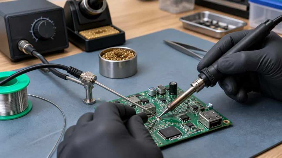
For typical hand-soldered electronics, a useful starting region is roughly 315 to 350°C (600 to 660°F) for tin-lead solder and about 340 to 370°C (645 to 700°F) for many common lead-free jobs. These are practical starting settings rather than universal limits. The appropriate tip temperature depends on the alloy, joint size, tip geometry, board construction, and the thermal performance of the soldering iron or station.
Start near the lower or middle part of a suitable range, then assess how readily the solder wets the heated surfaces. If a clean, tinned tip with good contact cannot heat the joint promptly, check the tip size, oxidation, flux, and thermal demand before raising the temperature.
Practical Starting Temperatures
| Soldering application | Suggested starting range | Practical adjustment |
|---|---|---|
| Tin-lead solder on ordinary PCB joints | 315 to 350°C (600 to 660°F) | Begin around the middle of the range and adjust for joint size and station behavior. |
| Lead-free solder on ordinary PCB joints | 340 to 370°C (645 to 700°F) | Use an appropriate tip with adequate contact area before moving toward the upper end. |
| Small pads and temperature-sensitive work | Lower portion of the alloy’s practical range | Use controlled contact, suitable flux, and a tip that reaches both surfaces without touching adjacent parts. |
| Ground planes, connectors, shields, and heavy leads | Upper portion of the practical range | A larger tip, greater thermal capacity, or controlled preheating may help more than a large temperature increase. |
These ranges are working references rather than universal requirements. Follow applicable solder, component, and equipment specifications when they provide process limits or recommended settings.
Why the Iron Is Set Above the Solder’s Melting Point
Common electronics solders melt at temperatures well below typical iron settings. For example, eutectic Sn63/Pb37 solder melts at approximately 183°C (361°F), while SAC305 lead-free solder has a liquidus temperature around 217°C (423°F).
An iron set near the solder’s melting point would usually transfer heat too slowly for practical hand soldering. Heat is continually moving from the tip into the component lead, pad, copper traces, and surrounding board. A higher tip setting creates enough temperature difference to bring the joint above the alloy’s melting and wetting temperature promptly.
The displayed temperature also represents the station’s sensor reading or control target rather than a guarantee that the contact surface of the tip remains at exactly that temperature during soldering. Tip construction, heater placement, station calibration, thermal recovery, oxidation, and joint mass all affect what happens at the work.
What Determines the Correct Temperature?
Solder Alloy
Lead-free alloys generally melt at higher temperatures than traditional tin-lead solder, which can increase the thermal demand of hand soldering. That does not mean the iron setting must rise by the same amount. A station with strong thermal recovery and a suitable tip may solder lead-free joints effectively at a moderate setpoint.
Specialized low-temperature or high-temperature alloys need different settings. Check the alloy label or technical data rather than trying to identify solder composition by appearance.
Tip Size and Geometry
A very fine tip has limited contact area and may transfer heat poorly to a pad connected to substantial copper, despite a high station setting.
A suitably sized chisel, bevel, hoof, conical, or other compatible tip should contact the joint effectively while preserving access around nearby components. Better contact allows heat to enter the joint quickly and can reduce the need for a higher setting or prolonged heating.
Joint Thermal Mass
A small surface-mount pad needs much less heat than a connector terminal, shield tab, thick wire, or through-hole joint tied to a ground plane. Large copper areas draw heat away from the contact point. Multilayer boards can also conduct heat into internal planes that are not visible from the surface.
If the iron repeatedly struggles on these joints, raising the setting may provide some improvement. A larger compatible tip, a station with better thermal recovery, or controlled board preheating may be a more effective correction.
Flux and Surface Condition
Oxidized leads, contaminated pads, and an oxidized tip interfere with heat transfer and solder wetting. Increasing temperature can burn flux faster while leaving the underlying problem unresolved.
Use compatible flux where needed, keep the plated tip clean and tinned, and make sure the parts are solderable. Avoid filing plated tips, since removing the protective plating can expose the underlying material and shorten tip life.
Component and PCB Limits
Components, connectors, wire insulation, pads, and laminates differ in heat tolerance. Excessive temperature or repeated heating can contribute to lifted pads, damaged insulation, delamination, or component damage. Sensitive parts may have soldering profiles or maximum exposure conditions in their documentation.
How to Fine-Tune the Setting
- Identify the solder alloy. Select a starting temperature suitable for tin-lead, lead-free, or specialty solder. Do not rely on spool color or joint appearance to determine composition.
- Choose a tip that fits the joint. The tip needs enough contact area to transfer heat efficiently while remaining clear of adjacent pads and components.
- Clean and tin the tip. A thin solder coating improves thermal contact and helps protect the working surface from oxidation.
- Heat both parts of the joint. Place the tip so it contacts the component lead and pad. Feed solder into the heated joint rather than melting a large amount directly on the tip.
- Observe the wetting behavior. Solder should melt and spread onto the intended surfaces without requiring prolonged heating. If it melts on the tip but refuses to wet the pad or lead, contamination, oxidation, inadequate flux, or poor thermal contact may be responsible.
- Change one variable at a time. Improve tip contact or move to a more suitable tip before making a large temperature increase. If adjustment is still needed, change the setting in modest increments and test again.
- Stop if the joint remains unresponsive. Repeated heating can damage the pad or component. Let the area cool, inspect the tip and surfaces, confirm the alloy and flux, and reassess the joint’s thermal demand.
Signs the Temperature May Be Too Low
A low setting is one possible cause of poor heat transfer, but similar symptoms can result from an undersized tip, weak thermal contact, oxidation, or a station that cannot recover effectively under load.
- Solder melts on the tip but takes too long to melt at the joint.
- The solder forms a bead and does not wet a clean, solderable pad or lead.
- Soldering performance drops sharply when the tip contacts a ground-connected or high-thermal-mass joint.
- The operator must hold the iron on the joint long enough for surrounding material to become excessively hot.
Long contact at a low temperature can expose the board and component to substantial total heat. The correction is still not automatically a hotter setting. First confirm tip condition, tip size, contact position, flux, surface cleanliness, and the thermal capacity of the tool.
Signs the Temperature May Be Too High
- Flux burns or disappears very quickly before the solder wets the surfaces effectively.
- The tip oxidizes rapidly and becomes difficult to keep tinned.
- Wire insulation softens, shrinks, or discolors near the joint.
- Pads begin to loosen or lift during soldering or rework.
- The board surface or nearby plastic shows visible heat damage.
Lower the setting and inspect the technique if these signs appear. A high temperature paired with poor tip contact can still produce slow soldering because only a small area of the tip is transferring heat effectively.
Temperature for Different Electronics Tasks
Through-Hole PCB Soldering
Ordinary resistor, capacitor, socket, and header joints often work within the practical range for the chosen alloy. Ground pins and large connector leads may require a wider tip or more thermal capacity than nearby signal pins. Use enough solder to wet the lead and pad without covering the joint in a large mound.
Surface-Mount Soldering
Small SMD joints often depend more on controlled solder quantity, accurate tip placement, suitable flux, and effective thermal contact than on extreme temperature. Select a tip that can contact the pad and termination efficiently without reaching neighboring parts. A moderately sized chisel may transfer heat more reliably than a needle-like tip in many situations.
Fine-pitch packages may call for techniques such as drag soldering, solder paste and reflow, or the use of a hot air rework station, depending on the package and repair context. Hot-air temperature settings are not directly interchangeable with soldering-iron settings because airflow, nozzle distance, board heating, and package mass change the process.
Wires and Connector Terminals
Thicker conductors and metal terminals can absorb substantial heat. A larger tip with suitable contact area usually helps. If wire insulation begins to soften before solder flows, stop and correct the heat-transfer problem rather than continuing to heat the joint.
Solder provides an electrical connection, but a wire exposed to pulling or repeated movement may also need appropriate mechanical support or strain relief.
Desoldering and Rework
Old solder, large copper areas, and lead-free assemblies can make rework thermally demanding. Fresh compatible solder and flux can improve wetting and thermal contact. Repeatedly increasing temperature while pulling on a component risks lifted pads and damaged plated holes. The solder should be fully molten before a lead or part is moved.
Temperature Setting Versus Wattage
Temperature and power describe different aspects of a soldering iron. The temperature setting establishes a control target. Available power and thermal design affect how well the tool maintains or restores tip temperature as heat moves into the joint.
A temperature-controlled station may apply additional heater power during contact while maintaining the same setpoint. This is why a capable station can handle a larger joint without requiring an extreme temperature setting. Nominal wattage by itself does not reveal tip-temperature accuracy, recovery behavior, or actual heat delivery at the joint.
Judging the Finished Joint
Allow the joint to cool without movement, then inspect it under suitable lighting and magnification. Look for wetting to the intended lead and pad, a stable joint shape, adequate coverage, and the absence of bridges, cracks, loose parts, or damaged pads.
Brightness is an unreliable pass-or-fail rule. Lead-free joints can appear different from tin-lead joints, and surface appearance varies with alloy and process. Visual inspection can reveal useful defects, while electrical testing and mechanical context may provide additional information. A continuity check can confirm a conductive path between test points when the test is appropriate, but it does not establish that the entire circuit or mechanical connection is correct.
A Practical Default
If you need a starting point and the solder alloy is known, about 330°C (625°F) is reasonable for many tin-lead electronics joints, while about 350°C (660°F) is a reasonable first setting for many lead-free jobs on a capable temperature-controlled station. These are starting points rather than target temperatures for every joint.
Prompt wetting with a clean, tinned, appropriately sized tip is a better target than chasing one exact display value. If the joint requires prolonged heating near the upper end of the practical range, reassess the tip, flux, surfaces, station performance, and copper mass before adding more temperature.

- Jesse
Jesse is the editor behind Soldering Gear, where he covers soldering irons, stations, rework equipment, and the tools that belong on a practical electronics bench. His work focuses on comparing product specifications, features, compatibility, and intended uses so readers can make more informed buying decisions.
- Best Cordless Soldering Iron: 9 Picks in 2026 September 28, 2026
- Best Portable Soldering Iron: 9 Picks in 2026 September 27, 2026
- What Temperature for Soldering Electronics? September 26, 2026
- Best Soldering Station for Beginners: 9 Picks in 2026 September 25, 2026
- Best Solder Fume Extractor: 9 Picks in 2026 September 24, 2026