How to Solder Electronics

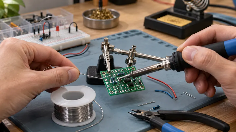
Learning how to solder electronics starts with one basic goal: heat the joint efficiently, apply solder to the heated parts, then allow the connection to cool without movement. A successful joint bonds the component lead, wire, or terminal to its pad or contact area while preserving the board, insulation, and nearby components.
Tools and Materials for Soldering Electronics
The exact setup depends on the size of the work and the components involved. A basic electronics bench commonly includes:
- A temperature-controlled soldering iron or station with a compatible tip
- Electronic solder suitable for the board and components
- Flux that is compatible with the solder and workpiece
- A damp sponge or brass tip cleaner approved for the iron
- A stand that keeps the hot iron secure between uses
- Side cutters for trimming through-hole leads
- Fine tweezers for small components
- A desoldering pump or solder wick for correcting mistakes
- Magnification and adequate lighting for small joints
- A multimeter for basic electrical checks
Confirm that the solder, flux, tip family, and cleaning materials are suitable for the specific equipment and assembly. Lead-containing and lead-free solder require compatible process settings and sensible hygiene practices. Component and PCB manufacturer guidance takes priority over general advice.
Prepare the Work Area
Secure the circuit board or wire so it cannot shift while the joint is heating. A PCB holder, helping-hands tool, or another stable support can reduce movement. Keep the iron stand close enough to reach without crossing over the workpiece.
Remove flammable materials from the immediate area, keep the iron cord away from the hot tip, and provide ventilation that moves flux fumes away from your face. Soldering smoke is primarily associated with heated flux and other process materials. It should not be treated as proof that lead has vaporized from ordinary soldering. Wash your hands after handling lead-containing solder, and avoid eating or drinking at the bench.
Disconnect power from the circuit before soldering unless a procedure specifically requires live measurements. Never solder a powered circuit as a shortcut for diagnosis. Protect sensitive components from electrostatic discharge with an appropriate ESD setup when their handling requirements call for it.
Set Up the Iron and Solder
Choose a tip that can transfer heat to the joint without blocking your view. A fine tip suits small pads and closely spaced contacts. A larger chisel or bevel tip can transfer heat more effectively to a ground plane, connector pin, or larger terminal. Tip selection depends on joint size, access, and the thermal mass of the work.
Set the station according to the solder alloy, tip, board, and component requirements. There is no single temperature that suits every electronics joint. A large copper area may need more heat transfer, while a small sensitive component may require careful control and short heating. Raising the setting excessively can damage pads, insulation, components, or the tip rather than solving poor heat transfer.
Clean the tip using the method recommended for the tip construction and station. A small amount of fresh solder on a clean plated tip helps create thermal contact. Do not file or aggressively abrade a plated electronics tip, since this can remove its working surface.
How to Solder Electronics Step by Step
-
Inspect the joint.
Identify the pad, lead, wire, or terminal that must be connected. Check for oxidation, contamination, damaged copper, nearby components, and spacing that could allow a solder bridge. If a component is polarized, verify its orientation before heating anything.
-
Secure the parts.
Keep the component lead, wire, or terminal in contact with the pad. Through-hole parts can be held by their leads, formed to fit the holes, or supported by a fixture. Small surface-mount parts may need fine tweezers or a stable PCB surface.
-
Apply the heated tip to the joint.
Touch the tip so it contacts the pad and the component lead or terminal at the same time. Heating only the pad or only the lead can produce poor wetting. A small amount of solder on the working face may improve thermal contact, but the joint itself should receive solder from the opposite side of the tip where access allows.
-
Feed solder to the heated metal.
Touch solder to the joint rather than coating the tip and transferring a blob. The solder should melt because the joint has reached a suitable temperature. If it melts only on the tip and beads up on the work, remove the solder, improve contact, check cleanliness, and reassess the setting or tip size.
-
Remove solder, then remove the iron.
Stop adding solder once the joint has adequate coverage and the surrounding features remain clear. Remove the solder first, then lift the iron away smoothly. Excess solder can hide poor wetting, connect adjacent pads, and make later inspection harder.
-
Hold the joint still while it cools.
Movement during solidification can create an irregular or cracked connection. Do not push, twist, or test the joint mechanically until the solder has cooled.
-
Trim and inspect where needed.
For through-hole work, trim the lead close to the joint with side cutters after the solder has cooled. Inspect the pad, lead, and nearby spacing under good light or magnification.
The process should produce controlled flow across the intended metal surfaces. Solder may form a concave fillet around a through-hole lead or a controlled connection between a surface-mount termination and its pad. The shape varies with the joint, solder alloy, flux, and amount of solder. Surface appearance alone does not prove that a connection is electrically and mechanically sound.
Adjusting Technique for Different Electronics Work
Through-Hole Components
Through-hole soldering usually involves a lead passing through a plated hole. Heat the lead and the pad together, then feed enough solder to wet the annular ring and lead. A properly formed connection covers the intended pad area without large lumps, voids, or contact with neighboring pads.
Trim leads after the connection has cooled. Avoid bending a hot lead against the pad, since force can stress the joint or lift damaged board material.
Surface-Mount Components
Surface-mount work requires smaller amounts of solder and more control. Tack one corner or terminal to hold the part, verify its alignment, then solder the remaining connections. For closely spaced pins, flux and a controlled amount of solder help reduce bridges. Solder wick can remove excess material, but repeated heating can damage pads or component terminations.
Small components can be damaged by mechanical pressure as well as heat. Use tweezers to position parts, and avoid dragging the tip across pads with unnecessary force.
Wires and Terminals
Strip only the length needed for the connection. Stray strands can create shorts, especially near connectors or exposed contacts. Keep insulation far enough from the joint to avoid melting, while preserving strain relief where the connector or assembly requires it.
For a wire-to-terminal connection, heat the terminal and conductor together, then apply solder until the strands are bonded without becoming an oversized rigid section. A soldered wire can still need a separate mechanical support or crimp, depending on the connector and application.
Large Copper Areas and Ground Connections
Large ground planes, chassis connections, shields, and heavy terminals draw heat away from the joint. A suitable larger tip, clean surfaces, appropriate flux, and an iron that can maintain its working temperature may help. Excessive temperature and prolonged heating are poor substitutes for suitable thermal transfer. Stop if the board begins to discolor, the pad moves, or nearby material shows heat damage.
How to Recognize and Correct Common Soldering Problems
| Observation | What it may indicate | What to check next |
|---|---|---|
| Solder beads up or refuses to spread | Oxidation, contamination, insufficient heating, unsuitable flux, or poor contact between the tip and joint | Clean the surfaces, refresh the tip, heat the pad and lead together, and confirm material compatibility |
| Solder melts on the tip but not on the joint | The tip is transferring heat poorly, the joint has high thermal mass, or the tip is too small | Improve contact, select a suitable tip, check the station setting, and reduce heat loss from the workpiece |
| Large blob with little visible connection | Too much solder or solder applied before the parts were properly heated | Remove excess solder with wick or a desoldering tool, then reheat the joint and inspect the pad and lead |
| Solder connects adjacent pads | A solder bridge, excessive solder, crowded spacing, or misalignment | Remove the bridge, check component alignment, add compatible flux if appropriate, and inspect under magnification |
| Joint moves, cracks, or looks disturbed | The parts moved during cooling, or the joint has mechanical stress | Check whether the pad or lead is damaged, secure the parts, and rework with controlled heating |
| Pad lifts from the board | Excessive heat, prolonged contact, force on the lead, or a previously weakened board | Stop heating, assess the trace and pad, and plan a repair rather than repeatedly reheating the area |
| Continuity is absent or intermittent | Poor wetting, a cracked joint, damaged trace, incorrect component placement, or a separate circuit fault | Inspect the entire connection path, test from accessible points, and verify the circuit without relying on one continuity reading |
A dull-looking joint is not automatically defective. Solder alloy and cooling behavior affect appearance. Look for poor wetting, cracks, disturbed surfaces, incomplete coverage, bridges, damaged pads, or movement rather than using brightness as the only test.
Inspect and Test the Finished Work
Begin with a visual inspection under strong light. Check for:
- Unconnected pads, leads, or wire strands
- Solder bridges between adjacent conductors
- Cracks, voids, or disturbed joints
- Excess solder that hides the connection
- Lifted pads, damaged traces, or overheated insulation
- Incorrect component orientation or misplaced parts
- Flux residue that interferes with inspection or the assembly requirements
Use a multimeter to check relevant connections and possible shorts with the circuit unpowered. A continuity result can confirm a low-resistance path between two test points, but it does not prove that the component is correct, the trace is undamaged elsewhere, or the circuit will operate as intended.
If the assembly passes visual and basic electrical checks, reconnect power using a controlled method appropriate for the circuit. Watch for unexpected current draw, heat, smell, or other signs of a fault. Disconnect power promptly if something behaves abnormally and inspect the circuit again.
Flux Residue and Cleanup
Flux helps solder wet the surfaces, but the correct cleanup method depends on the flux chemistry, board materials, components, and manufacturer guidance. Some residues are intended to remain, while others can affect insulation, appearance, reliability, or later coating processes.
Use a compatible cleaning material and avoid flooding parts that could trap liquid. Allow the board to dry fully before applying power. Never scrape solder mask or plated surfaces aggressively to remove residue. If the surface is difficult to clean or the residue type is unknown, identify the flux product before choosing a solvent.
Safety Practices That Prevent Common Damage
- Return the iron to its stand whenever it is not in use.
- Keep the hot tip away from skin, cords, insulation, and flammable materials.
- Wear eye protection during soldering, trimming leads, and removing solder.
- Use ventilation that carries flux fumes away from your breathing zone.
- Wash your hands after handling lead-containing solder and before eating.
- Keep powered circuits disconnected during soldering and rework.
- Use ESD precautions for components that require them.
- Allow boards, tools, and soldered parts to cool before handling or storing them.
- Stop reworking a joint if the pad shifts, the board darkens, or insulation begins to melt.
Good soldering depends on stable parts, clean surfaces, suitable heat transfer, controlled solder flow, and careful inspection. If a joint requires repeated heating, reassess the tip, flux, solder, component placement, and board condition before trying again.

- Jesse
Jesse is the editor behind Soldering Gear, where he covers soldering irons, stations, rework equipment, and the tools that belong on a practical electronics bench. His work focuses on comparing product specifications, features, compatibility, and intended uses so readers can make more informed buying decisions.
- Best Cordless Soldering Iron: 9 Picks in 2026 September 28, 2026
- Best Portable Soldering Iron: 9 Picks in 2026 September 27, 2026
- What Temperature for Soldering Electronics? September 26, 2026
- Best Soldering Station for Beginners: 9 Picks in 2026 September 25, 2026
- Best Solder Fume Extractor: 9 Picks in 2026 September 24, 2026