How to Solder Wires Together

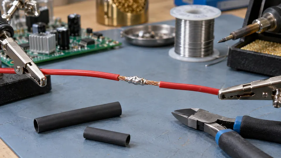
A reliable soldered wire splice starts with clean conductors, a stable mechanical connection, and enough heat transfer to let solder wet the wires. The iron should heat the conductors, then the conductors should melt the solder. Melting solder onto the tip and wiping it over cold wire usually produces a weak, poorly wetted joint.
The method below is suited to common copper and tinned-copper hookup wire. Aluminum wire, enamel-coated magnet wire, resistance wire, and other specialty conductors may require different preparation, flux, or joining methods.
Check Whether Soldering Is Appropriate
Disconnect every power source before cutting or stripping wires. Remove batteries where practical, unplug equipment, and account for circuits that may retain electrical charge.
A soldered splice works well for many low-voltage electronics, small appliances, test leads, and hobby projects. It may be unsuitable where electrical codes, equipment instructions, or industry practices call for approved terminals, connectors, or crimped splices. Vibration and repeated flexing also deserve attention because solder can wick along stranded wire and create a rigid section beside the joint.
For household wiring, vehicle safety systems, aircraft, medical equipment, or other safety-critical applications, use the specified connection method rather than assuming solder is acceptable.
Tools and Materials
- A temperature-controlled soldering iron or another iron capable of heating the splice efficiently
- A clean, tinned tip with enough contact area for the wire size
- Electronics-grade solder compatible with the work
- Flux suitable for electrical or electronic connections
- Wire strippers matched to the conductor size
- Heat-shrink tubing or another suitable electrical insulation method
- A stable holder, clamp, or helping-hands fixture
- Safety glasses
- A multimeter for checking the finished connection where appropriate
A small chisel or bevel tip often transfers heat to wire more effectively than a needle-like point. The best geometry depends on the conductor diameter, access, and thermal mass. Use a tip that can contact a meaningful portion of the splice without touching nearby insulation.
Rosin-based and other electronics fluxes are commonly used for copper wire. Plumbing solder and acid-based plumbing flux can leave corrosive residues and should not be used for ordinary electronics wiring.
How to Solder Wires Together
-
Cut and prepare the wires. Trim away damaged, oxidized, or heavily solder-soaked sections. Cut the ends cleanly so the finished splice does not contain broken strands.
-
Slide on the heat-shrink tubing. Place a suitable length of tubing over one wire before joining the conductors. Move it far enough from the work area that heat from the iron cannot shrink it prematurely.
-
Strip the insulation. Expose enough conductor to form the splice without leaving a long bare section. Use the correct stripper opening and avoid nicking solid wire or cutting strands from stranded wire. Damaged conductors have reduced strength and should be stripped again.
-
Inspect and clean the conductors. Copper should be free from insulation fragments, oil, heavy oxidation, and contamination. If the wire is visibly oxidized, cut back to clean conductor where possible. Repeated aggressive scraping can remove strands or damage plated conductors.
-
Form a stable mechanical connection. Cross the stripped ends, overlap them, and wrap each end around the opposite conductor. Keep the wraps close and controlled rather than creating a loose knot or large ball. The wires should remain together while being soldered, but the splice does not need to withstand hard pulling before solder is applied.
-
Secure the splice. Position the joint in a holder so it cannot roll, separate, or move while cooling. Arrange the insulation away from the tip. Avoid clamping so tightly that the wire insulation is crushed.
-
Prepare the iron. Bring the iron to a setting appropriate for the solder alloy, wire size, tip, and equipment. Clean the tip using the method intended for the iron, then apply a thin coating of fresh solder. This tinned surface improves thermal contact. Do not routinely file a plated tip.
-
Apply flux when needed. Many electronics solders contain a flux core, but a small amount of compatible additional flux can help on older or mildly oxidized copper. More flux is not a substitute for clean wire or adequate heating.
-
Heat the splice. Place the broad contact surface of the tip against both conductors. A small amount of molten solder between the tip and wire can improve heat transfer. Do not press hard. Firm, stable contact is more useful than pressure.
-
Feed solder into the heated wire. Touch the solder to the splice near the iron rather than feeding it entirely onto the tip. Once the wires are hot enough, solder should melt and flow between the strands and wrapped conductors. Add enough to wet the connection without burying it in a large blob.
-
Remove the solder, then the iron. Stop feeding solder once the splice is covered and wetted. Lift the iron away without disturbing the wires.
-
Let the joint cool naturally. Hold the wires still until the solder solidifies. Movement during cooling can leave cracks or an irregular, disturbed connection. Do not blow on the joint or handle it immediately.
-
Inspect and insulate the splice. Check the connection before covering it. Once satisfied, center the heat-shrink tubing over the entire exposed area and shrink it evenly using an appropriate heat source. Keep the heat source moving and protect nearby insulation and components.
What a Satisfactory Wire Joint Looks Like
Solder should wet the conductors and flow through the splice rather than sitting on top as a separate lump. The joint should have no loose strands, cracks, sharp projections, or exposed copper beyond the intended insulated area. Some outline of the conductors may remain visible beneath the solder.
Brightness is an unreliable quality rule. Lead-free and lead-containing alloys can cool with different surface appearances. A dull surface may be normal for a particular alloy, while a bright blob can still hide poor wetting underneath.
After cooling, apply a gentle pull to confirm that the wires are secure. This is a basic check rather than a destructive strength test. A continuity or resistance measurement can provide additional information with the circuit unpowered, but a continuity beep cannot confirm correct polarity, insulation integrity, current capacity, or adequate strain relief.
Prevent Heat Damage and Solder Wicking
Wire insulation may soften or retreat if the splice is heated too slowly. A larger contact surface, clean tip, fresh flux, and suitable iron often produce a better joint with less total heating than a very fine tip at an excessive setting.
Long heating can also draw solder farther along stranded wire. This creates a stiff section that concentrates bending where the solder ends. Keep solder confined to the splice as much as practical, and support the wire so normal movement does not repeatedly flex that transition point.
Connectors commonly provide a crimped strain-relief area around the insulation. An inline soldered splice lacks that feature unless the assembly adds mechanical support. Route or secure the cable so pulling and vibration are carried by the cable support, enclosure, clamp, or harness rather than by the soldered conductors.
Common Problems and Corrections
| What you observe | Likely issue | What to check |
|---|---|---|
| Solder forms a bead and does not spread across the copper | The wire may be contaminated, oxidized, insufficiently fluxed, or too cool | Stop heating, let the area cool, then inspect and clean the conductor. Confirm that the flux and solder are suitable and that the tip contacts both wires effectively. |
| Solder melts on the tip but will not flow into the splice | Heat is reaching the solder before it reaches the conductors | Use a tip with better contact area, place it against both wires, and feed solder to the heated splice. |
| Insulation shrinks back or melts | The heating period is too long, the tip has poor contact, or the iron lacks effective heat delivery | Reassess tip size, cleanliness, flux, and joint preparation. Replace wire if insulation damage leaves an unsafe or unreliable section. |
| The joint has cracks or an irregular surface | The wires may have moved as the solder solidified | Improve the fixture. Reflow the connection once with suitable flux if the conductors and insulation remain undamaged. |
| The splice is covered by a large solder ball | Excess solder may be hiding incomplete wetting | Use flux and controlled heat to remove or redistribute excess solder, then confirm that solder has bonded to the conductors. |
| Strands break beside the joint during use | Solder wicking, repeated flexing, or poor strain relief may be concentrating stress | Replace the damaged section and add cable support. A properly selected crimp connector may suit a high-vibration location better. |
If solder still refuses to wet after a controlled second attempt, stop and reassess the material. Continued heating can char insulation, oxidize the conductors, and damage nearby parts. The wire may have an incompatible coating or may require a joining process other than ordinary electronics soldering.
Variations for Different Wire Arrangements
Inline splices
An inline splice joins two wire ends along the same path. Keep it narrow enough for insulation to fit while leaving sufficient conductor overlap for a stable joint. Stagger multiple splices in a cable where space permits. Staggering reduces bulk and lowers the chance that adjacent joints will contact each other if insulation shifts or becomes damaged.
Pigtail and branch connections
For a pigtail, several conductors meet at one point. Arrange the stripped ends into a compact mechanical connection before soldering, and confirm that heat reaches every conductor. Larger bundles have more thermal mass and may require a larger tip or more capable iron. Adding temperature without improving contact can overheat the outer wires while the center remains poorly wetted.
Very fine wires
Fine stranded conductors are easy to nick, overheat, or stiffen with excess solder. Strip them with a suitable tool, use minimal exposed length, and apply solder sparingly. Magnification can help reveal severed strands and insulation damage.
Pre-tinned wires
Factory-tinned wire can usually be joined with the same basic procedure. Fresh solder and compatible flux help the existing tinning merge into the splice. Thickly pre-tinning bare wire before twisting can make it difficult to form a close mechanical connection, so tin individual ends only where the joint design calls for it.
Finish the Work Safely
Keep the iron in a stable stand whenever it is out of your hand. Wear eye protection, especially while cutting wire or handling springy strands. Work with ventilation appropriate for the flux and process, and avoid placing your face directly over rising fumes.
Flux fumes come primarily from heated flux and related process materials, rather than solder metal simply boiling away under ordinary soldering conditions. If using lead-containing solder, keep food and drinks away from the work area, avoid touching your face, and wash your hands after handling it.
Before restoring power, verify that the heat-shrink tubing covers all exposed conductor, adjacent wires cannot short together, polarity is correct, and the cable has adequate support. Inspect the surrounding insulation for accidental tip contact or heat damage.

- Jesse
Jesse is the editor behind Soldering Gear, where he covers soldering irons, stations, rework equipment, and the tools that belong on a practical electronics bench. His work focuses on comparing product specifications, features, compatibility, and intended uses so readers can make more informed buying decisions.
- Best Soldering Iron for SMD: 9 Picks in 2026 October 15, 2026
- Best Hot Air Rework Station for SMD: 9 Picks in 2026 October 14, 2026
- What Tools Do You Need for Soldering Electronics? October 13, 2026
- Best USB-C Soldering Iron: 9 Picks in 2026 October 12, 2026
- How to Choose Solder for Electronics October 11, 2026