How to Desolder Electronics

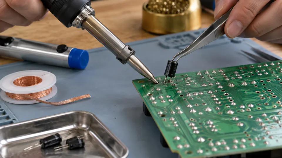
Desoldering removes solder from a joint so a component, wire, or connector can be released without damaging the circuit board. The central challenge is to melt the joint completely, remove the liquid solder efficiently, and stop heating before pads, traces, insulation, or components are harmed.
Learning how to desolder electronics requires matching the method to the joint. Desoldering braid works well for small amounts of solder and pad cleanup. A solder sucker is useful for many through-hole joints. A powered desoldering tool is often the practical choice for multi-pin components, while hot air or heated tweezers may suit surface-mount parts.
Prepare the Board Before Applying Heat
Disconnect all external power and remove batteries where practical. Stored energy may remain in capacitors after power is removed, so follow the equipment manufacturer’s service procedure for checking and discharging the circuit. Do not assume a disconnected board is electrically safe.
Secure the assembly on a stable, heat-resistant surface. Good lighting and magnification make it easier to distinguish the component lead, pad, solder mask, and nearby parts. Position the board so the molten solder can be reached without twisting the iron or placing your hand in an awkward path.
- Wear eye protection, especially when using a spring-loaded solder sucker.
- Keep the hot iron in a stable stand when it is idle.
- Use suitable ventilation for fumes produced by heated flux and process materials.
- Keep food and drinks away from the work area. Wash your hands after handling lead-containing solder.
- Use appropriate ESD precautions when working around static-sensitive devices.
Before removing anything, record the component’s orientation. Photograph the board and mark pin 1, polarity, connector alignment, and wire positions where necessary. This prevents a successful removal from becoming an incorrect reinstallation.
Choose a Desoldering Method
| Method | Suitable applications | Main limitation |
|---|---|---|
| Desoldering braid | Removing solder from pads, correcting bridges, and cleaning small joints | Can heat the pad for too long if the braid is dry, oxidized, or poorly positioned |
| Manual solder sucker | Single through-hole joints with accessible molten solder | May require several attempts and can jolt delicate pads |
| Powered desoldering tool | Connectors, ICs, switches, and other multi-pin through-hole parts | Requires correct nozzle size, cleaning, and regular maintenance |
| Hot air | Many surface-mount packages and groups of joints that must melt together | May heat or displace nearby components if airflow and shielding are poorly controlled |
| Heated tweezers | Two-terminal SMD parts such as resistors and capacitors | Access and tip alignment depend on component size and surrounding clearance |
| Low-melting removal alloy | Multi-lead packages where extending the molten state aids removal | Residue must be removed according to the product process before normal soldering |
Keep compatible flux and fresh solder available. Adding a small amount of fresh solder to an old joint can improve thermal contact and introduce active flux. This is particularly helpful when the existing solder is oxidized or the iron struggles to transfer heat into the joint.
Select a tip that can reach the joint while providing useful contact area. A very sharp conical tip may touch only a tiny point and transfer heat poorly. A suitably sized chisel, bevel, hoof, or conical tip may work better, depending on access, pad geometry, copper area, and nearby components. The tip must also be compatible with the iron or handpiece.
How to Desolder a Through-Hole Joint
-
Inspect the joint and identify the lead.
Determine whether the lead is bent against the pad, clinched on the opposite side, or mechanically attached to a terminal. Straightening a lead while the solder is solid can lift a pad or damage a plated hole. Leave it alone until the solder has melted.
-
Clean and tin the iron tip.
A clean, lightly tinned tip transfers heat more effectively than a dry or oxidized surface. Choose a temperature appropriate for the solder alloy, joint size, board construction, and station behavior. Raising the setting should not replace proper tip contact, flux, or suitable equipment.
-
Apply flux and refresh the joint if necessary.
Place a small amount of compatible flux on the joint. If the solder resists melting or appears heavily oxidized, add fresh solder. The added solder creates a broader thermal bridge between the tip and the joint.
-
Melt the entire solder joint.
Touch the tip so it contacts both the lead and the soldered pad. The solder around the full lead circumference should become liquid before extraction begins. Pressing harder does little to improve heating and may damage the board.
-
Remove the molten solder.
For a manual pump, place the nozzle close to the joint without driving it into the pad, then trigger the pump while the solder remains fully liquid. For a powered desoldering tool, position the nozzle over the lead, allow the solder to melt, and use gentle circular movement only if the tool’s instructions support that technique.
-
Let the board cool briefly, then inspect the hole.
A cleared plated hole usually shows separation between the lead and the hole wall. Test the lead with very light movement using tweezers. It should move independently. If it remains fixed, more solder may be hidden on the opposite side or inside the plated hole.
-
Release every connection before lifting the component.
Repeat the process for each pin. Never use the component body as a lever against the board. Once all leads are free, lift the part straight out with minimal force.
Large ground planes, shields, transformer pins, and heavy terminals draw heat away quickly. A larger tip with better contact area may transfer heat more effectively than a fine tip at a higher setting. If the equipment cannot keep the joint molten long enough for extraction, stop and reassess rather than repeatedly heating the same pad.
Using Desoldering Braid Correctly
Braid removes liquid solder through capillary action. It is useful for cleaning pads after a component has been removed, flattening excess solder on SMD lands, and clearing the remaining film around a through-hole lead.
- Cut a clean section of braid and apply compatible flux if the braid is not adequately fluxed.
- Place the braid directly on the solder to be removed.
- Set the iron tip on top of the braid, using enough contact area to heat the braid and joint efficiently.
- Watch for solder to flow into the braid. The wetted section will change appearance as solder spreads through it.
- Lift the iron and braid away together while the solder is still molten.
- Trim off the solder-filled portion before the next attempt.
Do not drag cooled braid across a pad. Once solder solidifies through the braid, pulling it sideways can tear copper from the board. Braid also carries heat along its length, so hold it with tweezers or keep your fingers well away from the heated section.
If the braid sticks, return the iron to it and wait for the captured solder to remelt. Remove both together without force.
Removing Surface-Mount Components
Surface-mount removal requires all attached terminals to become free at nearly the same time. Heating one lead and pulling upward while other joints remain solid places stress on pads and component terminations.
Two-Terminal Parts
For a resistor, capacitor, diode, or similar two-terminal component, heated tweezers can melt both ends simultaneously. Another approach is to add enough solder to improve heat transfer, then alternate rapidly between the two ends while applying gentle lifting force with tweezers. The component should release while both joints are liquid. If one pad remains anchored, stop pulling and reheat it.
Multi-Lead Packages
Hot air, low-melting removal alloy, or package-specific heating tools are commonly more suitable for multi-lead devices. Apply compatible flux and heat the leads evenly. With hot air, use airflow that will not blow neighboring parts out of position. Heat-sensitive connectors, plastic housings, and nearby components may require shielding or a different removal method.
Lift the package only after every joint has released. A corner that remains attached suggests incomplete melting. Continued lifting can peel the pad or trace from the board.
After removal, use flux and braid to level the pads. Avoid pressing the braid into softened board material. Clean residues according to the flux or removal-alloy instructions, then inspect the land pattern before installing a replacement.
Desoldering Wires, Lugs, and Connectors
Wire joints often include mechanical wrapping, crimping, hooks, or strain-relief features. Removing the solder does not necessarily release the wire. Examine the connection before pulling.
Support the wire with tweezers or pliers, melt the joint fully, and separate the conductors without splashing solder. If the wire is hooked through a terminal, unhook it while the solder is liquid or after enough solder has been removed to permit gentle mechanical release.
Check insulation near the joint for melting, shrinking, or embrittlement. A replacement wire or connector should have suitable strain relief where movement or pulling is expected. Solder should not serve as the sole mechanical support for a frequently flexed cable.
What to Do When the Joint Will Not Clear
| What you observe | What may be happening | Next action |
|---|---|---|
| Solder melts only where the tip touches | The tip has insufficient contact area, the joint has high thermal mass, or the tip surface is oxidized | Clean and tin the tip, improve its position, or use a suitable larger geometry |
| The solder looks liquid, but the pump removes very little | The solder may have started cooling, the nozzle may be poorly positioned, or the pump may be clogged | Service the pump, refresh the joint with flux and solder, then make one controlled attempt |
| Braid does not absorb solder | The braid may be oxidized, short of flux, or receiving inadequate heat | Use a fresh section, add compatible flux, and improve tip contact on the braid |
| A lead remains fixed after the visible solder is removed | Solder may remain inside the plated hole, the lead may be bent, or solder may be present on the other side | Inspect both sides under magnification and remove the remaining solder without forcing the lead |
| The solder quickly returns across the hole | The pump timing may be late, or molten solder may be drawn back from the opposite side | Keep the full joint liquid and position the suction nozzle closer before triggering |
| The pad changes color, moves, or begins separating | The adhesive bond or laminate may be heat-damaged | Stop heating. Allow the board to cool and assess whether pad or trace repair is required |
Several unsuccessful attempts on one joint are a signal to pause. Check the tip, nozzle, flux, tool maintenance, board access, and thermal demand. Repeated heat cycles can weaken pad adhesion and damage plated through-holes. A powered extraction tool, preheating method, or component-sacrificing approach may be safer for a valuable board.
If the old component is already defective and its leads are accessible, cutting the component body away can allow each lead to be removed individually. Protect the board and nearby parts from the cutting tool, control loose lead fragments, and avoid cutting into the PCB. This approach sacrifices the component to reduce stress on the board.
Inspect the Board After Removal
Examine both sides of the work area under adequate light and magnification. Look for:
- Lifted, loose, or missing pads
- Cracked or separated traces
- Damaged plated through-holes
- Solder bridges and loose solder particles
- Scratched solder mask exposing unintended copper
- Burned laminate or heat-damaged nearby components
- Flux or removal-alloy residue that requires cleaning
A clean-looking area can still contain an electrical fault. Use continuity and resistance checks where they are appropriate for the circuit, with power disconnected. Verify that intended connections remain continuous and adjacent conductors are not shorted. Circuit components connected across the test points can affect meter readings, so interpret results using the schematic or known circuit layout.
Before fitting a replacement, confirm that each hole or pad is usable and that the replacement orientation is correct. If a pad has lifted or a plated connection has failed, repair the conductor path before soldering the new part. Forcing a lead through a partly blocked hole can tear the remaining plating and push solidified solder into the board.

- Jesse
Jesse is the editor behind Soldering Gear, where he covers soldering irons, stations, rework equipment, and the tools that belong on a practical electronics bench. His work focuses on comparing product specifications, features, compatibility, and intended uses so readers can make more informed buying decisions.
- Best Soldering Iron for Microsoldering: 9 Picks in 2026 November 10, 2026
- Best Soldering Station for PCB Repair: 9 Picks in 2026 November 9, 2026
- How to Desolder Electronics November 8, 2026
- Best Hot Air Rework Station for PCB Repair: 9 Picks in 2026 November 7, 2026
- Soldering Iron Tip Shapes Explained November 6, 2026