How to Use a Soldering Iron

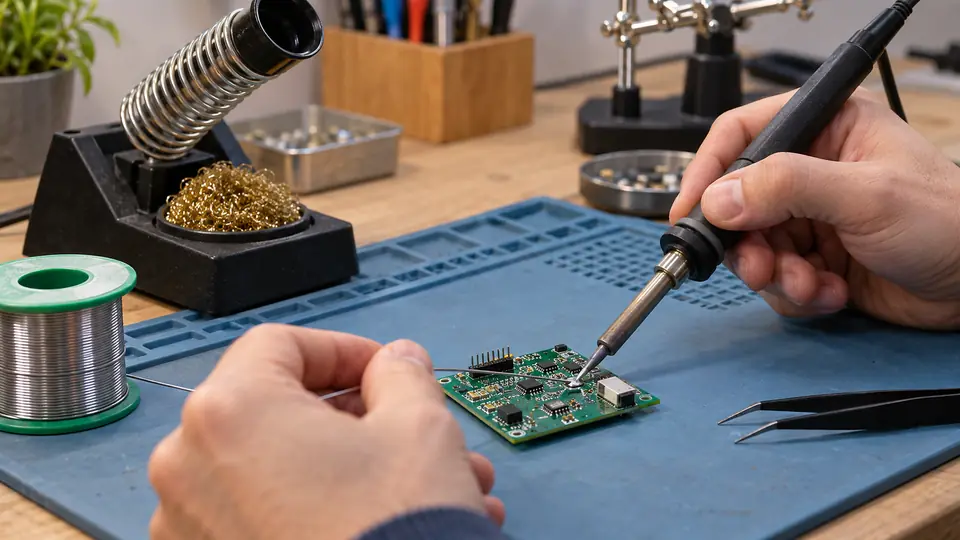
Using a soldering iron successfully depends on transferring heat into the parts being joined, then feeding solder to those heated surfaces. The solder should flow across the connection rather than sit as a blob on the iron’s tip. Clean surfaces, a suitable tip, flux, and stable work positioning make that process much easier.
The procedure below focuses on common electronics work, including through-hole components and wires. Surface-mount parts, heat-sensitive components, and damaged PCB pads may require finer tools and more specialized techniques.
Prepare the Tool, Materials, and Work Area
Set up the work before turning on the iron. Trying to hold a wire, component, solder, and hot tool at the same time often produces unstable joints or accidental burns.
- Soldering iron or temperature-controlled station: The iron should have enough thermal capacity for the joint without being excessively large or awkward.
- Compatible soldering tip: A small chisel tip is useful for many electronics joints because its flat surface transfers heat efficiently. Very fine conical tips can struggle with larger joints.
- Solder: Choose an alloy and diameter appropriate for the work. Electronics solder commonly contains a flux core, but additional compatible flux can improve wetting.
- Iron stand: The hot iron should return to a stable, heat-resistant holder whenever it leaves the joint.
- Tip-cleaning material: Brass wool or a damp cellulose sponge can remove light oxidation and old flux residue.
- Work holder: A PCB vise, fixture, or suitable clamp keeps the connection from moving while the solder cools.
- Eye protection: Small droplets of molten solder or clipped wire ends can travel unexpectedly.
- Ventilation or fume extraction: Position airflow so soldering fumes move away from your face without cooling the joint excessively.
- Cutters and wire strippers: These are needed for preparing wires and trimming component leads.
Keep paper, solvents, loose cables, and other flammable or obstructive materials away from the iron. Route its power cord where it cannot catch on the work or pull the stand over.
If the solder contains lead, avoid eating or drinking at the bench and wash your hands after handling it. The visible fumes generated during ordinary electronics soldering primarily come from heated flux, rather than vaporized lead. Suitable ventilation remains important because flux fumes can be irritating.
Choose a Suitable Tip and Temperature
The tip should contact enough of the joint to transfer heat efficiently. A tip that is too small may lose heat when it touches a large lead, terminal, connector, or copper area. A tip that is unnecessarily large can obstruct access and heat nearby surfaces.
Temperature requirements depend on the solder alloy, tip geometry, joint size, copper area, board construction, component sensitivity, and behavior of the iron. Follow the solder, component, and equipment manufacturers’ guidance where available. Start with a suitable setting for the materials, then judge performance by how readily the joint reaches soldering temperature.
If solder refuses to flow, raising the temperature is rarely the best first response. Check these factors first:
- The tip is clean, wetted with solder, and free from heavy oxidation.
- The tip has enough contact area for the joint.
- The work surfaces are clean and solderable.
- Suitable flux is present.
- The iron has enough thermal capacity for the connection.
Excessive temperature can accelerate tip oxidation, burn flux prematurely, damage PCB laminates, lift pads, melt insulation, or stress components. A properly selected tip can often deliver heat more effectively at a moderate setting than a tiny tip used at an excessive temperature.
How to Use a Soldering Iron Step by Step
- Secure and prepare the connection.Insert the component, position the wire, or arrange the terminal so the parts remain mechanically stable. Strip wire insulation without nicking the conductor. Oxidized terminals or conductors may need appropriate cleaning before soldering. Avoid scraping PCB pads or plated component leads aggressively.
- Turn on the iron and let it stabilize.Place the iron in its stand while it heats. A temperature-controlled station may indicate when it has reached the selected setting. Basic irons without temperature control need enough time to reach a stable operating condition.
- Clean and tin the tip.Wipe the hot tip briefly through brass wool or across a suitably damp sponge. Apply a small amount of fresh solder so the working surface has a thin, continuous coating. This coating protects the tip and improves thermal contact.
A tip covered in dry, dark oxidation will transfer heat poorly. Repeated hard scraping can damage the protective plating, so plated tips should not be filed or sanded as routine maintenance.
- Place the tip against both parts of the joint.For a through-hole connection, contact the component lead and copper pad together. For a wire on a terminal, touch both the conductor and terminal. Use the broad working face of the tip where possible rather than pressing with the very point.
A tiny amount of solder between the tip and joint can create a thermal bridge and improve heat transfer. This is different from loading the tip with a large solder blob and wiping it onto the connection.
- Feed solder into the heated joint.Touch the solder to the joint near the tip. The heated work should melt it. Feed only enough to wet and cover the required surfaces without hiding the shape of the connection or flooding adjacent conductors.
If the solder melts only when pressed directly against the iron, the joint may still be too cool, contaminated, poorly fluxed, or receiving inadequate tip contact.
- Remove the solder, then remove the iron.Stop feeding solder once the connection has enough coverage. Withdraw the solder wire first, followed by the iron. This sequence reduces the chance of leaving solder wire stuck to the joint.
- Hold the connection still while it solidifies.Movement during cooling can produce cracks, an irregular surface, or an unstable mechanical connection. Do not blow on the joint or move the lead to test it while the solder is solidifying.
- Inspect and test the result.Look for wetting across the surfaces that should be joined, a clear connection between the lead and pad or terminal, and adequate spacing from nearby conductors. Remove clipped lead ends only after the joint has cooled enough to handle safely.
Adjust the Technique for the Type of Joint
Through-Hole Components
Heat the component lead and PCB pad together, then feed solder at their junction. The solder should wet the pad and rise around the lead without creating a large ball. Avoid pushing down hard with the iron, since pressure does little to improve heat transfer and may damage a weakened pad.
Large ground planes draw heat away from the joint faster than small isolated pads. A broader tip, suitable thermal capacity, or an appropriate station setting may be needed. Prolonged heating with an undersized tip can be harder on the board than efficient heating with a properly matched tip.
Wires and Terminals
Twist stranded wire only enough to keep the strands organized. Apply compatible flux where needed, then pre-tin the conductor if the connection method benefits from it. Excessive tinning can make stranded wire rigid beyond the terminal and may prevent it from fitting correctly.
Whenever possible, secure the wire mechanically before soldering. Heat the wire and terminal together, then allow solder to flow between them. Keep insulation far enough from the heated area to reduce melting or shrinkage.
Solder should not serve as the sole source of mechanical support where the joint will experience repeated movement or pulling. Strain relief, crimp features, clamps, or suitable connector construction may be necessary.
Small Surface-Mount Parts
Surface-mount work usually calls for a fine but thermally effective tip, controlled solder quantity, good magnification, and stable tweezers. One common manual method is to place a small amount of solder on one pad, reheat it while positioning the component, and then solder the remaining connections.
Small parts can move from surface tension or excess pressure. Apply flux, use minimal solder, and avoid chasing the component around the board with the tip. Fine-pitch devices may be better handled with drag soldering, solder paste, hot air, or reflow equipment, depending on the package and repair context.
How to Judge the Finished Joint
A useful visual inspection considers wetting and joint geometry rather than brightness alone. Some solder alloys naturally produce a less reflective surface, so a dull appearance does not automatically indicate failure.
Check for:
- Solder that has flowed onto the intended pad, lead, wire, or terminal rather than forming a separate ball
- No visible cracks or signs that the connection moved during cooling
- No bridges between conductors that should remain separate
- No loose strands projecting from a wire joint
- No lifted pads, scorched laminate, melted connector bodies, or damaged insulation
- Enough solder to form the connection without burying adjacent features under a large mass
Visual inspection can reveal many problems, but it does not prove complete electrical and mechanical integrity. A continuity check can confirm that two test points are connected, provided the circuit is unpowered and the test is appropriate for the assembly. It cannot establish that the entire circuit is correct, and parallel circuit paths can complicate meter readings.
Fix Common Soldering Problems
| Symptom | Possible causes | What to check or change |
|---|---|---|
| Solder beads up instead of spreading | Oxidized surfaces, insufficient flux, incompatible materials, or inadequate joint heating | Clean the surfaces appropriately, apply compatible flux, verify that the parts are solderable, and heat both sides of the connection |
| Solder melts on the tip but not on the joint | Poor tip contact, an undersized tip, a cool joint, or heavy oxidation | Use the working face of a clean, tinned tip and select a tip with more contact area if the joint has greater thermal mass |
| Joint looks cracked or irregular | Movement during cooling, poor wetting, contamination, or repeated reheating | Secure the work, add compatible flux if needed, reflow the joint carefully, and hold it still as it solidifies |
| Solder bridge connects adjacent pads | Too much solder, poor control, or insufficient flux distribution | Apply flux and remove excess solder with solder wick or a desoldering tool while protecting nearby pads |
| Tip turns dark and will not hold solder | Oxidation, excessive temperature, long idle periods, or unsuitable cleaning | Use the manufacturer’s recommended tip-cleaning method, lower the setting where practical, and keep a light solder coating on the tip |
| Pad begins lifting from the board | Excessive heat, repeated rework, force on the lead, or previous damage | Stop heating and reassess the repair. Continuing can separate the pad or trace further |
| Wire insulation shrinks or melts | Long heating time, excessive temperature, a tip that is too small, or insulation with limited heat resistance | Improve thermal transfer, use a suitable tip, prepare the joint beforehand, and reduce unnecessary contact time |
Protect the Tip During and After Use
Tip condition has a direct effect on soldering performance. Clean the tip briefly when residue interferes with wetting, then apply fresh solder. Constant wiping removes the protective solder layer and exposes the hot surface to oxidation.
During pauses, return the iron to its stand with a light coating of solder on the tip. Some stations provide a standby temperature that slows oxidation while keeping the tool ready. Use this feature according to the equipment instructions.
At the end of the job:
- Clean loose flux residue from the tip without aggressive abrasion.
- Apply enough fresh solder to cover the tip’s working surfaces.
- Switch off or unplug the iron according to its controls.
- Leave it in the stand until fully cool.
- Clean the assembly only with a method compatible with the flux, PCB, components, and cleaning agent.
Flux residue does not always require the same treatment. Some residues are intended to remain, while others should be removed for process, inspection, electrical, or cosmetic reasons. Follow the flux manufacturer’s guidance and consider the requirements of the finished assembly.

- Jesse
Jesse is the editor behind Soldering Gear, where he covers soldering irons, stations, rework equipment, and the tools that belong on a practical electronics bench. His work focuses on comparing product specifications, features, compatibility, and intended uses so readers can make more informed buying decisions.
- Best Cordless Soldering Iron: 9 Picks in 2026 September 28, 2026
- Best Portable Soldering Iron: 9 Picks in 2026 September 27, 2026
- What Temperature for Soldering Electronics? September 26, 2026
- Best Soldering Station for Beginners: 9 Picks in 2026 September 25, 2026
- Best Solder Fume Extractor: 9 Picks in 2026 September 24, 2026